Follow these steps to record and compare your viscosity tests:
-
1. Enter Batch Details (Blue Section):
Fill in the Date, Reference, Batch Number, and Temperature in the top (Blue) section. -
2. Set the Baseline (Red Section):
To compare this batch against a standard, you must load data into the Red section.
Option A: Use the “Saved Baselines Library” (Yellow box) to load a preset.
Option B: Scroll to a previous test in the Log Book and click “Set as Baseline”. -
3. Perform 3 Tests:
Enter your readings in the Blue inputs.
• Test 1: Initial reading.
• Test 2: After 1st time lapse (e.g., 5 mins).
• Test 3: After 2nd time lapse (e.g., 10 mins). -
4. Analyze:
Check the Time/Shear Profile graph. If the line goes UP, your material is thickening over time (Thixotropic). -
5. Save:
Click “Add to Log” to save the entry to your session history list below.
Note: Always ensure you use the same wire and bob size when comparing results.
2025 Update: Major Advancements to the 3D-Printed Torsion Viscometer
The 2025 update introduces several significant improvements to the 3D-printed torsion viscometer, with the most notable being a new white base that simplifies the leveling process for users.
Key Design Enhancements
Improved Mounting Mechanism: An aluminum collar has been added to the mounting system, increasing both durability and stability.
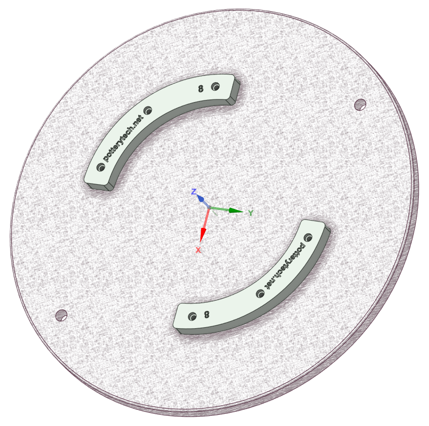
Redesigned Scale Platform: The scale platform has been completely redesigned for improved functionality. It now includes reference pin markers and a white mounting gauge, providing a clear and designated area for precise placement. This makes measurement and adjustment much more intuitive and accurate.
First-of-Its-Kind Feature: This update includes an exclusive innovation not found on any previous torsion viscometer. The design was led by Michael G. Parry-Thomas.
Single-Module Construction: The platform is now 3D printed as a single, precision-engineered module, enhancing reliability and alignment.
Project Background: Why I Built a 3D-Printed Viscometer for Ceramic Glaze
In Christmas 2022, I received a Voxelab Aquila X2 3D printer from my family. One of my hobbies is making ceramic pottery for friends and family. With the 3D printer, I saw an opportunity to design and create my own custom tools for ceramic work.
Although I had no prior experience with 3D printing or CAD software, I’ve worked with many printing processes over the years. I specialized in ceramic silkscreen printing, which gave me a strong foundation in using different types of machinery. Interestingly, I found that many of the settings on 3D printers are similar to those on traditional printing equipment.
Purpose of the Viscometer
You can buy ceramic glaze either as a powder or as a ready-mixed brush-on glaze. I wanted a way to accurately measure glaze viscosity using a laboratory-grade instrument. However, these tools can be very expensive.
So, I decided to build my own using the 3D printer.
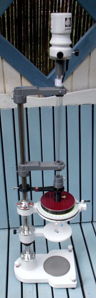
The result is a fully functional torsion viscometer for measuring the viscosity of ceramic pottery glaze and casting slip. It’s highly accurate, and every component can be replaced or upgraded as needed.
- Parts not printed consist of :-
- Purchased from eBay
- 1. Stainless steel shaft.
- 1. Perspex tube.
- 1. Flywheel Top stainless Stainless steel disc.
- 1. Sample cup small stainless steel disc.
- 1. Small disc in the base. Thumb screws bolts. (Brass – stainless steel)
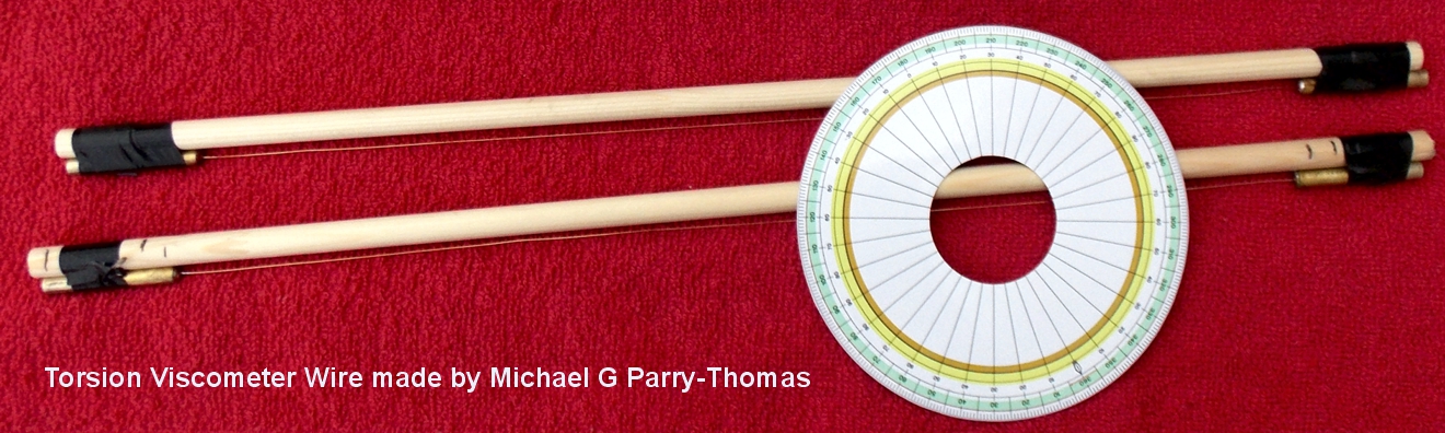
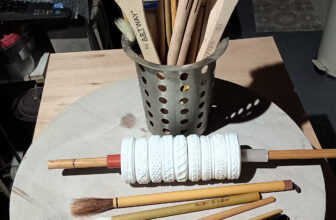
- 1. 30swg torsion viscometer wire (This has been made in house – wire ends are designed to be reused)
Viscometer accessory box
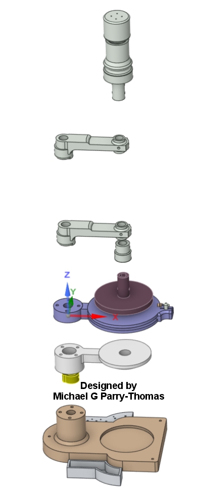
- Printed parts:-
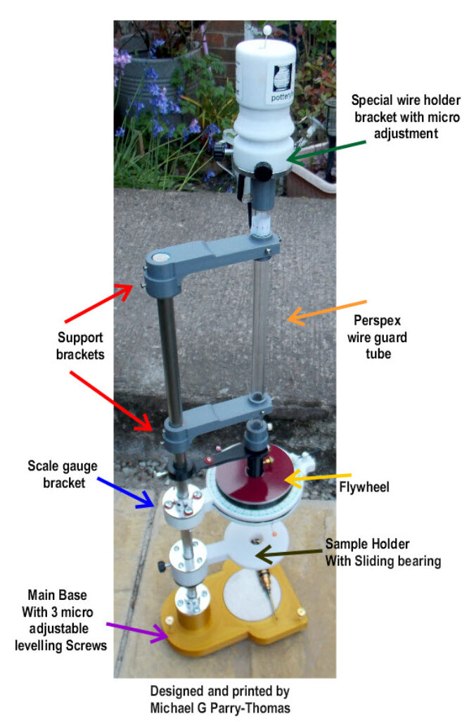
2. Support brackets ………………… (Hold the Perspex wire guard tube) - 1. Scale gauge bracket ……………. (Hold the printed vinyl scale)
- 1. Sample holder bracket …………. (Allows the sample to be held in position)
- 1. Sample stop ………………………… (This stop allows you to set the sample bracket height)
- 1. Main base ……………………………. (The main base has 3 micro adjustable levelling)
1.wire holder ……………………………. (Special wire holder bracket with micro adjustment)- 1.Adapter ring ………………………….. (This was added so you could use a commercial spring wire)
- 1.Sliding centring wire guard …….. (This allows you to slide section of the wire guard to assist in levelling)
- 1.Flywheel ……………………………….. (Customisable can add stainless steel weight discs, brass locking screw for securing bobs)
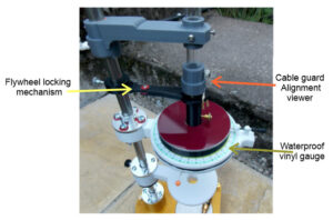
- 1.Flywheel locking mechanism …… (Fully adjustable indicator pointer locking holder)
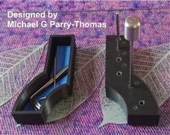
2.Accessory trays …………………….. (designed to locate on the side of the main base to store any Allen keys and also bobs
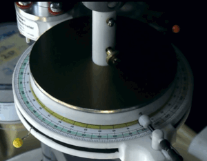
1.Waterproof vinyl gauge…………… (can also be used with removable logging dial)
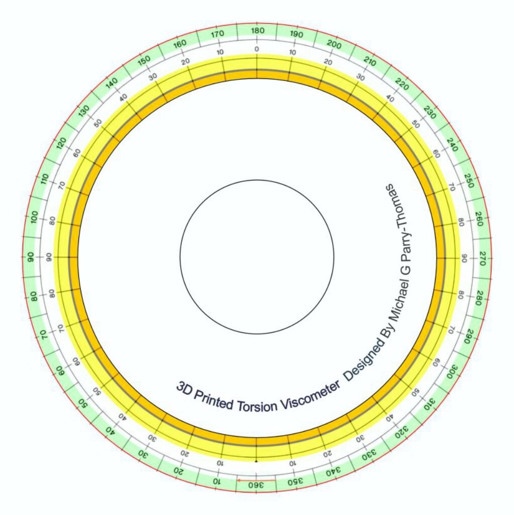
The scale was created using Front Designer 3 then imported into CorelDRAW
- Features
Levelling:-The instrument has 3 brass levelling adjusters (The printed base has double brass inserts holding each of the thumb brass micro levelling adjusters )
Wire adjustment zero calibrating:- (The top wire housing holder has an adjustment ring which you use to turn the flywheel pointer to calibrate to the zero mark on the scale. This is then locked in place with two thumb locking screws.
Cable guard Alignment viewer:-(This is located at the end of the Perspex wire guard the function is to allow you easy access to connect the wire to the flywheel and gives you a visual aid on aligning the instruments flywheel .When the instrument is level and the dial indicator is reading zero on the gauge you slide down the cover and lock in place with a thumb screws .
Sample Bob:-(Installing and changing the sample Bob is done by using a brass thumbscrew- Sample cup Holder:- The sample cup holder has been designed so the sample can be raised Vertical and locked into place with a thumbscrew .There is also an additional locking ring stop this is used so you can adjust the height of the sample cupholder this allows more flexibility when positioning your sample.